|
|
|
|
 |
|
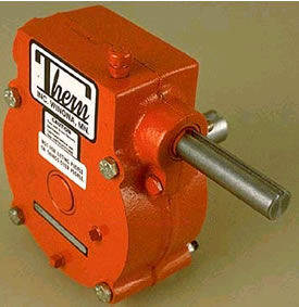
WORM
GEAR SPEED REDUCERS - DIMENSIONS (in)
|
|
|
|
46H |
46P |
47H |
47P |
48H |
48P |
|
input shaft dia. |
.62 |
.62 |
.62 |
.75 |
1.00 |
.75 |
|
output shaft dia. |
.75 |
.75 |
1.00 |
1.00 |
1.50 |
1.50 |
|
A |
7.62 |
5.44 |
10.12 |
5.62 |
13.60 |
7.94 |
|
B |
4.62 |
6.81 |
6.75 |
8.94 |
12.10 |
15.00 |
|
C |
5.06 |
5.06 |
7.25 |
6.94 |
12.25 |
12.25 |
|
D |
1.81 |
1.81 |
2.91 |
2.91 |
5.44 |
5.44 |
|
E |
3.81 |
3.81 |
5.56 |
5.56 |
10.06 |
10.06 |
|
F |
5.94 |
5.94 |
5.94 |
5.94 |
7.81 |
7.81 |
|
G² |
7.25 |
7.25 |
7.25 |
7.25 |
12.25 |
12.25 |
|
H² |
7.59 |
7.59 |
7.59 |
7.59 |
12.69 |
12.69 |
|
J |
.88 |
3.06 |
.88 |
3.06 |
.88 |
4.06 |
|
K |
5.31 |
3.06 |
7.50 |
3.06 |
9.75 |
4.06 |
|
input shaft keyway |
- |
.19 x 3.00 |
- |
.19 x 3.00 |
- |
.19 x 4.00 |
|
output shaft keyway |
- |
.19 x 3.00 |
- |
.25 x 3.00 |
- |
.38 x 3.00 |
|
|
|
Important:
It is the owner's or operator's
responsibility to determine the suitability
of the equipment to its intended use. Study
all applicable codes, manuals, and
regulations. Be sure to read the Owner's
Manual supplied with the equipment before
operating it. |
Dimenstions
are for reference only and subject to change without notice |
| ²
Handles are adjustable, dimension shown is for maximum
handle length. |
|


