 |
ENGINEERED
STEEL PRODUCTS |
| Priced
Full Line Products Catalog |
20
Technology Way • West Greenwich, RI 02817
Toll free:(800) 421-0314 • In RI:(401) 272-4570 • Fax:(401)
421-5679 |
 |
|
|
 |
Back to Product Category
LoPro Commercial Series Air Curtains
Electric Heated
|
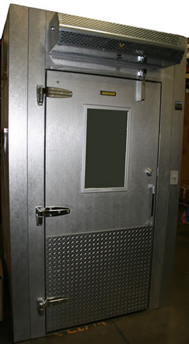
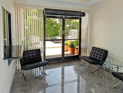
The
Most Cost-effective Environmental and Sanitation Barrier You’ll Never
See |
FREE
FREIGHT |
| FOR
ALL AIR CURTAINS SHIPPED TO LOCATIONS WITHIN THE 48 CONTIGUOUS UNITED STATES |
|
 |
|
|
|
| The
Most Cost-Effective Environmental and Sanitation Barrier You'll Never See |
|
|
|
| AIR
CURTAIN BENEFITS |
|
LOPRO
COMMERCIAL AIR CURTAINS
SERIES FEATURES |
•
Reduces Energy Costs And Consumption
• Creates Effective Environmental Separation
• Maintains Interior Building Temperatures
• Provides Low Operational Costs
• Minimizes Dirt, Dust, And Fumes
• Prevents Flying Insects From Intruding
• Offers An Unobstructed View, Enhancing Safety |
|
|
• Aesthetically
Pleasing “Low Profile” 8" Design
• Low Noise Level For Quiet Operation
• Easy To Install
• Low Maintenance
• NSF Models Available (Contact us.) |
|
|
|
DOOR
HEIGHTS |
|
|
| DOOR
WIDTHS |
|
|
Environmental
Separation up to 8'
Flying Insect Control up to 7' |
| 25"
to 144" |
|
|
|
|
|
|
| HEATING
OPTIONS |
|
|
| Electric
and Steam/Hot Water |
|
|
|
|
|
|
|
 |
 |
|
|
|
|
Model
No. |
Width
of Door |
Door
Height |
FLA
(Ampacity) Single Phase |
Sound
dBA |
Weight
(lbs) |
115V |
208V/230V |
LPV36 |
36" |
7'
- 8' |
2.4 |
1.2
/1.2 |
49 |
30 |
LPV42 |
42" |
7'
- 8' |
2.4 |
1.2/1.2 |
50 |
33 |
LPV48 |
48" |
7'
- 8' |
2.4 |
1.2/1.2 |
52 |
37 |
LPV60 |
60" |
7'
- 8' |
2.6 |
1.4/1.4 |
53 |
45 |
LPV72 |
72" |
7'
- 8' |
2.6 |
1.4/1.4 |
53 |
56 |
LPV84-2 |
84" |
7'
- 8' |
4.8 |
2.4/2.4 |
53 |
66 |
LPV96-2 |
96" |
7'
- 8' |
4.8 |
2.4/2.4 |
53 |
74 |
LPV108-2 |
108" |
7'
- 8' |
5 |
2.6/2.6 |
54 |
82 |
LPV120-2 |
144" |
7'
- 8' |
5.2 |
2.6/2.6 |
54 |
90 |
LPV144-2 |
144" |
7'
- 8' |
5.2 |
2.8/2.8 |
54 |
112 |
|
|
LOPRO
(LPV) 1/6 HP VARIABLE SPEED ELECTRIC
HEATED
COMMERCIAL MODELS
|
|
|
|
|
|
 |
|
NOTES: |
|
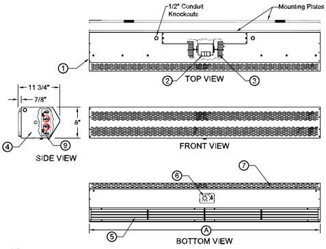
1. This
product is designed to meet the
National Electric Code (NEC) and is ETL
Listed for the US and Canada. |
|
2. Continuous
duty, direct drive, variable
speed, double shaft motors with automatic
thermal overload protection. Overload
protects motor from burnout, minimizing
maintenance costs. |
|
3. Blower
wheels are rust proof and
dynamically balanced to provide quiet
operation, while maintaining high air velocity. |
|
4. Low
profile appearance. Overall height is
8" and overall depth is 11 3/4". |
|
5. Air
directional vanes, with 40° sweep front
to back, compensates for drafts. |
|
6. Mounted
adjustable speed controller knob
allows air velocity to meet a wide range of
field conditions. Units greater than 72" are
double units joined with a 2" mounting
bracket located in the center, field installed.
The speed controller will be located on the
right hand unit and controls both units. |
|
7.
All units have a self contained one piece
cabinet, fire retardant and corrosion proof
point lock metal, double protected with
Obsidian Black rust preventative electro-
static powder coating . |
|
|
|
|
|
|
|
|
8.
Normally closed door limit switch(es) is
optional and field installed. Switch to be
mounted so the air curtain turns on
as the door begins to open. |
|
 |
|
|
|
|
|
9.
Units greater than 72" require dual power
supplies, one for each air curtain. |
|
|
|
|
|
| Model No. |
Unit Length
(A) |
| LPV236-1E |
36" |
| LPV242-1E |
42" |
| LPV248-1E |
48" |
| LPV260-1E |
60" |
| LPV272-1E |
72" |
| LPV284-2E |
86" |
| LPV296-2E |
98" |
| LPV2108-2E |
110" |
| LPV2120-2E |
122" |
| LPV2144-2E |
146" |
|
|
|
|
TYPICAL
INSTALLATION |
|
|
1- lnstall Mounting
plate(s) using the pre-drilled
holes. |
|
|
2 - Securely attach
cabinet to mounting plate
using tabs as guides, when fully inserted
secure with (2) #10 Tek Screws.
"CAUTION": Unit
to be mounted with
the lowest moving part at least 7 Feet above
floor or grade level. |
|
|
3 - lnstall optional
door limit switch(es) to door
header. (8) |
|
|
4
- Connect internal wires from unit to supply
power. |
|
|
|
|
|
|
|
|
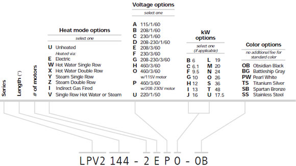
Understanding
Series Order Codes |
 |
|
| Standard
Features: |
|
|
| •
Easy Install Mounting Plate |
|
| •
18 month warranty |
|
| •
1/6 HP Direct Drive |
|
| •
Made in USA |
|
| •
Variable Speed Controller |
|
|
|
| •
8" Low Profile Metal Design |
Protection |
|
| •
Standard color: |
•
Environmental: 8' |
|
|
 |
|
|
•
Flying Insect: 7' |
|
|
|
|
|
|
|
|
 |
|
|
|
|
|
|
|
|
|
|
|
 |
|
Order
Online, by Phone, or by E-Mail |
|
|
|
~ Add
items to your online shopping cart ~
Click the Model No. of the item you wish
to purchase. |
|
|
PRICING
FOR LOPRO (LPV) VARIABLE SPEED
COMMERCIAL ELECTRIC HEATED MODELS |
Model
No. -
Color
Code (std) |
Voltage |
kW |
Air
Volume
(max.)
| Length |
Height |
Depth |
Full
Load
Draw |
Heater
Draw |
Motor
Draw |
Avg.
Velocity |
Weight
(lbs.) |
Price |
|
208/1/60 |
6.1kW |
900cfm |
36" |
8" |
11
3/4" |
31amps |
~ |
~ |
1800fpm |
35 |
$2,458 |
|
230/1/60 |
6.1kW |
900cfm |
36" |
8" |
11
3/4" |
28amps |
~ |
~ |
1800fpm |
35 |
$2,458 |
|
208/3/60 |
10kW |
900cfm |
36" |
8" |
11
3/4" |
29amps |
~ |
~ |
1800fpm |
35 |
$2,458 |
|
230/3/60 |
10kW |
900cfm |
36" |
8" |
11
3/4" |
26amps |
~ |
~ |
1800fpm |
35 |
$2,458 |
|
460/3/60 |
10kW |
900cfm |
36" |
8" |
11
3/4" |
~ |
13amps |
2.4amps |
1800fpm |
35 |
$2,458 |
|
460/3/60 |
10kW |
900cfm |
36" |
8" |
11
3/4" |
~ |
13amps |
1.2amps |
1800fpm |
35 |
$2,458 |
|
208/1/60 |
8kW |
1050cfm |
42" |
8" |
11
3/4" |
40amps |
~ |
~ |
1800fpm |
40 |
$2,565 |
|
230/1/60 |
8kW |
1050cfm |
42" |
8" |
11
3/4" |
36amps |
~ |
~ |
1800fpm |
40 |
$2,565 |
|
208/3/60 |
10kW |
1050cfm |
42" |
8" |
11
3/4" |
29amps |
~ |
~ |
1800fpm |
40 |
$2,565 |
|
230/3/60 |
10kW |
1050cfm |
42" |
8" |
11
3/4" |
26amps |
~ |
~ |
1800fpm |
40 |
$2,565 |
|
460/3/60 |
10kW |
1050cfm |
42" |
8" |
11
3/4" |
~ |
13amps |
2.4amps |
1800fpm |
40 |
$2,565 |
|
460/3/60 |
10kW |
1050cfm |
42" |
8" |
11
3/4" |
~ |
13amps |
1.2amps |
1800fpm |
40 |
$2,565 |
|
208/1/60 |
8kW |
1200cfm |
48" |
8" |
11
3/4" |
40amps |
~ |
~ |
1800fpm |
45 |
$2,617 |
|
230/1/60 |
8kW |
1200cfm |
48" |
8" |
11
3/4" |
36amps |
~ |
~ |
1800fpm |
45 |
$2,617 |
|
208/3/60 |
13kW |
1200cfm |
48" |
8" |
11
3/4" |
37amps |
~ |
~ |
1800fpm |
45 |
$2,617 |
|
230/3/60 |
13kW |
1200cfm |
48" |
8" |
11
3/4" |
34amps |
~ |
~ |
1800fpm |
45 |
$2,617 |
|
460/3/60 |
13kW |
1200cfm |
48" |
8" |
11
3/4" |
~ |
16amps |
2.4amps |
1800fpm |
45 |
$2,617 |
|
460/3/60 |
13kW |
1200cfm |
48" |
8" |
11
3/4" |
~ |
16amps |
1.2amps |
1800fpm |
45 |
$2,617 |
|
208/1/60 |
9.5kW |
1500cfm |
60" |
8" |
11
3/4" |
47amps |
~ |
~ |
1800fpm |
50 |
$2,688 |
|
230/1/60 |
9.5kW |
1500cfm |
60" |
8" |
11
3/4" |
43amps |
~ |
~ |
1800fpm |
50 |
$2,688 |
|
208/3/60 |
13kW |
1500cfm |
60" |
8" |
11
3/4" |
37amps |
~ |
~ |
1800fpm |
50 |
$2,688 |
|
230/3/60 |
13kW |
1500cfm |
60" |
8" |
11
3/4" |
34amps |
~ |
~ |
1800fpm |
50 |
$2,688 |
|
460/3/60 |
13kW |
1500cfm |
60" |
8" |
11
3/4" |
~ |
16amps |
2.6amps |
1800fpm |
50 |
$2,688 |
|
460/3/60 |
13kW |
1500cfm |
60" |
8" |
11
3/4" |
~ |
16amps |
1.4amps |
1800fpm |
50 |
$2,688 |
|
208/1/60 |
9.5kW |
1800cfm |
72" |
8" |
11
3/4" |
47amps |
~ |
~ |
1800fpm |
56 |
$2,795 |
|
230/1/60 |
9.5kW |
1800cfm |
72" |
8" |
11
3/4" |
43amps |
~ |
~ |
1800fpm |
56 |
$2,795 |
|
208/3/60 |
13kW |
1800cfm |
72" |
8" |
11
3/4" |
37amps |
~ |
~ |
1800fpm |
56 |
$2,795 |
|
230/3/60 |
13kW |
1800cfm |
72" |
8" |
11
3/4" |
34amps |
~ |
~ |
1800fpm |
56 |
$2,795 |
|
460/3/60 |
13kW |
1800cfm |
72" |
8" |
11
3/4" |
~ |
16amps |
2.6amps |
1800fpm |
56 |
$2,795 |
|
460/3/60 |
13kW |
1800cfm |
72" |
8" |
11
3/4" |
~ |
16amps |
1.4amps |
1800fpm |
56 |
$2,795 |
|
Model
No. -
Color
Code (std) |
Voltage |
kW |
Air
Volume
(max.)
| Length |
Height |
Depth |
Full
Load
Draw |
Heater
Draw |
Motor
Draw |
Avg.
Velocity |
Weight
(lbs.) |
Price |
|
208/3/60 |
20kW |
2100cfm
| 84" |
8" |
11
3/4" |
58amps |
~ |
~ |
1800fpm |
76 |
$3,965 |
|
230/3/60 |
20kW |
2100cfm
| 84" |
8" |
11
3/4" |
53amps |
~ |
~ |
1800fpm |
76 |
$3,965 |
|
460/3/60 |
20kW |
2100cfm
| 84" |
8" |
11
3/4" |
~ |
25amps |
4.8amps |
1800fpm |
76 |
$3,965 |
|
460/3/60 |
20kW |
2100cfm
| 84" |
8" |
11
3/4" |
~ |
25amps |
2.4amps |
1800fpm |
76 |
$3,965 |
|
208/3/60 |
26kW |
2400cfm
| 96" |
8" |
11
3/4" |
75amps |
~ |
~ |
1800fpm |
86 |
$4,325 |
|
230/3/60 |
26kW |
2400cfm
| 96" |
8" |
11
3/4" |
68amps |
~ |
~ |
1800fpm |
86 |
$4,325 |
|
460/3/60 |
26kW |
2400cfm
| 96" |
8" |
11
3/4" |
~ |
33amps |
4.8amps |
1800fpm |
86 |
$4,325 |
|
460/3/60 |
26kW |
2400cfm
| 96" |
8" |
11
3/4" |
~ |
33amps |
2.4amps |
1800fpm |
86 |
$4,325 |
|
208/3/60 |
26kW |
2700cfm
| 108" |
8" |
11
3/4" |
75amps |
~ |
~ |
1800fpm |
88 |
$4,686 |
|
230/3/60 |
26kW |
2700cfm
| 108" |
8" |
11
3/4" |
68amps |
~ |
~ |
1800fpm |
88 |
$4,686 |
|
460/3/60 |
26kW |
2700cfm
| 108" |
8" |
11
3/4" |
~ |
33amps |
5amps |
1800fpm |
88 |
$4,686 |
|
460/3/60 |
26kW |
2700cfm
| 108" |
8" |
11
3/4" |
~ |
33amps |
2.6amps |
1800fpm |
88 |
$4,686 |
|
208/3/60 |
26kW |
3000cfm
| 120" |
8" |
11
3/4" |
75amps |
~ |
~ |
1800fpm |
95 |
$5,047 |
|
230/3/60 |
26kW |
3000cfm
| 120" |
8" |
11
3/4" |
68amps |
~ |
~ |
1800fpm |
95 |
$5,047 |
|
460/3/60 |
26kW |
3000cfm
| 120" |
8" |
11
3/4" |
~ |
33amps |
5.2amps |
1800fpm |
95 |
$5,047 |
|
460/3/60 |
26kW |
3000cfm
| 120" |
8" |
11
3/4" |
~ |
33amps |
2.8amps |
1800fpm |
95 |
$5,047 |
|
208/3/60 |
26kW |
3600cfm
| 144" |
8" |
11
3/4" |
75amps |
~ |
~ |
1800fpm |
110 |
$5,407 |
|
230/3/60 |
26kW |
3600cfm
| 144" |
8" |
11
3/4" |
68amps |
~ |
~ |
1800fpm |
110 |
$5,407 |
|
460/3/60 |
26kW |
3600cfm
| 144" |
8" |
11
3/4" |
~ |
33amps |
5.2ams |
1800fpm |
110 |
$5,407 |
|
460/3/60 |
26kW |
3600cfm
| 144" |
8" |
11
3/4" |
~ |
33amps |
2.8amps |
1800fpm |
110 |
$5,407 |
|
Note:
A separate 115v or 208v power source required for motors.
O= 460/8/60, 115/1/60
P= 460/3/60, 208/1/60 |
|
 |
|
OB |
|
TS |
|
PW |
|
|
|
|
|
|
|
|
| Optional
Color Available - Std. Production Color is Obsidian Black (matte) See add-on prices below. |
|
|
|
|
|
|
|
Prices
for Colors That are not Standard for the Series
(add these prices to price of Electric Heated
Lopro Comm. air curtain above) |
| Length of Unit |
25" |
36" |
42" |
48" |
60" |
64" |
72" |
84" |
96" |
108" |
120" |
144" |
| TS |
|
|
|
|
|
|
|
|
|
|
|
|
| PW |
|
|
|
|
|
|
|
|
|
|
|
|
|
|
|
 |
|
Order
Online, by Phone, or by E-Mail |
|
|
|
~ Add
items to your online shopping cart ~
Click the Part No. of the item you wish to
purchase. |
|
|
|
LOPRO
ACCESSORIES - ELECTRIC HEATEAD |
| DOOR SWITCHES |
| Automatic
on/off control of air curtain as door is opened and closed |
| LINE VOLTAGE |
| Part # |
Package |
Price |
| 99-014 |
Steel Mechanical Universal Surface-Mounted Plunger/Roller Switch |
$141.50 |
| 24 VOLT CONTROL |
| Part # |
Package |
Price |
| 99-018 |
Commercial Magnetic Reed Switch Only Plastic • Surface-mounted
NOTE: Used with control packages J0023 or J0024 for double doors |
$66.10 |
| CONTROL PACKAGES - Combination packages of door switches, controllers,
time delays, and thermostats |
| LINE
VOLTAGE |
| Part # |
Package |
Price |
|
Analog
Thermostat Remote-mounted |
$165.10 |
| FILTERS |
| Part No. |
Filters |
Price |
| FLTR |
Aluminum Mesh Filter 1/4' Internal-mount • Set of 2 • (size):
Specify size in inches |
$3.10/per in. |
|
|
HEATED
PRODUCTS SUPPLEMENT |
|
|
|
|
|
NOTE |
|
Before
proceeding, refer to the units specific IOM Manual for safety, installation
and
start information. Verify proper voltage to the product per local and
NEC codes.
Ensure proper rotation for units with three phase motors. |
|
|
|
|
|
| Electrically
Heated Products |
|
 |
|
|
|
|
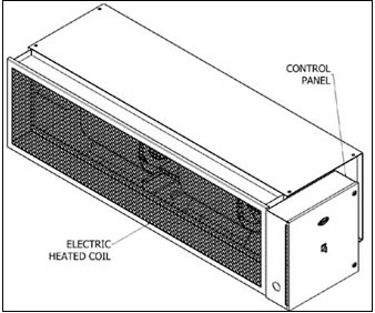
Electrically
heated products must be mounted on the
inside of the building. Electrically heated products come
standard with a thermostat (provided and shipped loose,
unless ordered as factory pre-mounted) and is to be field
installed. |
|
|
Note:
1. Electrically heated Low Profile units come with internally
mounted controls and available with optional 24 volt
or
240 volt thermostat. |
|
|
2.
Electrically heated Standard, High Velocity and Extra
Power units include a motor control panel mounted on
the right-hand side of the unit, as standard, and a remote
24 volt thermostat with On/Off switch with terminals
provided. |
|
|
|
FIG.
1 |
|
3.
Electrically heated Wind Stopping and WindGuard units
include an electric heater control panel mounted on the
right hand side, as standard (FIG. 1). Optional motor/
unit control panel available, which includes a remote
24 volt thermostat with On/Off switch with terminals
provided. |
|
|
|
|
|
|
 |
|
|
|
|
The
thermostat should be mounted as close to the
product’s discharge air flow as possible in order to best
sense the discharged air temperature around the door
opening. Connect proper voltage to the product per local
and NEC codes. (FIG. 2) |
|
|
|
|
|
Thermal
overload protection is built into the heater coil
assembly/assemblies. In the event of an overload condition,
electrical power will be disconnected from the heater coil.
Upon diagnosing the problem, electrical power can be re-
instated to the heater coil(s) by manually resetting the
thermal overload lever(s) or buttons(s) located in the unit
or panel. |
|
|
|
FIG. 2 |
|
|
|
|
|
|
|
|
To
operate multiple units mounted side by side, utilizing
a single door switch and single thermostat, a master/slave
configuration is required. (FIG. 2) |
|
|
|
|
LOW
PROFILE (LPV) VARIABLE SPEED AND
LOW PROFILE (LPN) NSF COMMERCIAL SERIES |
|
Installation,
Operation and Maintenance Manual |
Please
read and save these instructions. Read carefully before attempting to assemble,
install, operate or maintain the
product described. Protect yourself and others by observing all safety information.
Failure to comply with these
instructions could result in personal injury and/or property damage. Retain
these instructions for future reference. |
|
|
|
|
|
|
|
| OVERVIEW |
|
|
 |
|
|
|
|
|
|
|
|
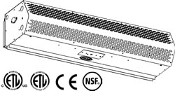
Our
Air Curtains are designed to cover door openings,
providing both temperature control/environmental
separation and flying insect control, when the building’s
doors are opened. Typical installation heights are: LoPro
Series; LPV (Variable Speed) models (Environmental up
to 8’), LPN (NSF for Customer Entrances) models |
|
|
|
|
(Flying Insect Control up
to 7’) and LPN-F (NSF for
Counter Top/Pass Through Windows) models (Flying
Insect Control up to 4’ from Counter Top) All NSF
Certified Models (ETL) should be mounted at the Flying
Insect Control heights referenced above. The units are
typically wall mounted horizontally above the door
opening. They can also be suspended from the ceiling.
The units are ETL Listed, Canada and US, for either an
inside or outside mount and ETL Sanitation Certified.
Heated units must be mounted on the inside or the
protected side of the opening. The motors used in all
LoPro Series are 1/6HP. |
|
|
|
|
|
|
|
|
|
|
 WARNING WARNING |
|
To
reduce the risk of fire, electric shock or injury to
persons, observe the following. |
|
A.
Always disconnect, lock and tag power source
before installing or servicing product. |
|
B.
Installation work or electrical wiring must be done
by qualified person(s) in accordance with all ap-
plicable codes and standards, including fire-rated
construction. |
The
LoPro Series come standard with a stamped air intake
screen(s). The LPV models can be configured with an
aluminum mesh filter(s) as an option. The LPN models
25”, 28” and 30” and all LPN-F models come standard
with an aluminum mesh air intake filter(s) in conjunction
with the punched air intake screen(s). |
|
C.
The combustion airflow needed for safe operation
of fuel burning equipment in the area may
be
affected by the product’s operation.
Follow the
heating equipment manufacturer’s guideline
and
safety standards, such as those published
by the
National Fire Protection Agency (NFPA), the
American Society of Heating, Refrigeration
and
Air Conditioning Engineers (ASHRAE) and local
code authorities. |
|
|
|
| GENERAL
SAFETY INFORMATION |
|
|
Use
this product only in the manner intended by the
manufacturer. If you have any questions, contact the
manufacturer. Only qualified personnel should install
this product. Installing personnel should have a clear
understanding of these instructions and should be
aware of general safety precautions. Improper
installation can result in electric shock, possible injury
due to coming in contact with moving parts, as well as
other potential hazards. |
|
|
|
|
D.When
cutting or drilling into a wall or ceiling, be
careful not to damage electrical wiring and other
hidden utilities. |
|
|
|
|
|
|
|
|
|
 WARNING WARNING |
|
|
|
Precaution
should be taken in explosive atmospheres. |
|
|
|
|
|
|
|
|
|
|
|
|
|
|
|
|
Note: If the holes provided on the bottom of the unit
and the bottom of the wall mounting plate do not align,
remove the unit and re-install. The holes on the bottom
channel of the wall mounted plate must be on the
bottom. |
|
 WARNING WARNING |
|
|
When
servicing the product, motor may be hot enough to
cause pain or injury. Allow motor to cool before servicing. |
|
|
|
|
|
| RECEIVING
AND INSPECTION |
|
|
|
|
|
|
|
|
|
|
 |
|
|
Upon
receiving the product, check to make sure all items
are accounted for by referencing the Bill of Lading to
ensure all items were received. Inspect each carton for
shipping damage before accepting delivery. Notify the
freight carrier if any damage is noticed. The carrier will
make notification on the delivery receipt acknowledging
any damage to the product. All damage should be noted
on all copies of the Bill of Lading which is countersigned
by the delivering carrier. A Carrier Inspection Report
should be filled out by the carrier upon arrival and a report
given to the Traffic Department. If damaged upon arrival,
file a claim immediately with the carrier. Any physical
damage to the unit after acceptance is not our
responsibility. |
|
|
|
|
|
|
|
| UNPACKING |
|
|
|
|
|
|
|
|
|
|
Verify
that all parts, components and accessories, and the
correct quantities of each have been received. If any items
are missing, report shortages to Mars Air Systems directly
to arrange for obtaining the missing items. Again, verify
quantities received against those on the Bill of Lading only,
as multiple shipments may be involved. |
|
FIG.
1 |
|
|
|
|
|
 |
|
|
|
|
|
|
|
| INSTALLATION |
|
|
|
|
Typical
Mounting – Wall or Ceiling Mounted
Horizontally Above the Door Opening |
|
|
|
|
1.
Remove the air intake grille(s) and/or air intake filter(s)
from the product and set aside. Gently remove all
packaging materials, hardware and all other accessories
from interior of unit prior to operating. Severe unit
damage will occur if these items are not removed prior
to operation. |
|
|
|
|
2.
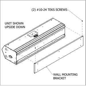
Lay unit on its top with directional vanes pointing up
and remove the Tek Screws from the wall mounting
plate, just behind the discharge nozzle, and remove
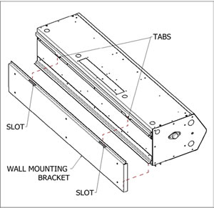
the mounting plate from the unit. (FIG. 1) Measure
the mounting plate and center it over the opening.
The air curtain shall be equal to or greater than
the
width of the opening. |
|
|
|
|
|
|
|
FIG.
2 |
|
|
|
|
|
|
|
5.
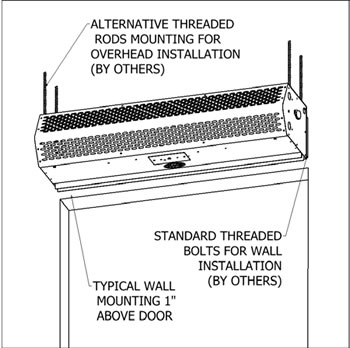
Mount the product such that the discharge is 1” above
the opening and all obstacles. (FIG. 3) |
|
|
|
Note:
If the product is installed higher than the
recommended 1” above the opening, then it must be
moved 3/8” away from the wall for every 1” that it is
moved up. Any void between the wall and the product
must be sealed, by others, to optimize performance. |
|
3.
Install the mounting plate(s) above the opening.
Multiple pre-punched 7/16” mounting holes are
provided for your convenience. These holes must
be utilized to secure the product to the wall. All
hardware is field provided by others. |
|
|
|
|
|
|
|
|
|
6.
Use four (4) threaded rods for overhead installation
or four (4) threaded bolts for wall installation. All
hardware is field provided by others. (FIG. 3) |
|
4.
Align the tabs on the rear of the unit with the slots
provided on the wall mounting plate (FIG. 2). The
bottom flange on the unit must also drop in the
bottom channel of the wall mounting plate. Replace
the Tek Screws to secure the unit in place. |
|
|
|
|
|
|
|
|
|
|
NOTE |
|
 |
|
For
accessory installation, reference Accessory Installation
Supplement.
For heated products, reference Heated Products
Supplement. |
|
|
|
|
START-UP |
|
This
product has been assembled and tested at the factory
prior to shipping. The following procedures should be
performed to assure its performance. Before continuing
with the start-up, it is important to recognize the safety
controls furnished with the unit. |
|
|
|
|
 WARNING WARNING |
|
Prevent
hazard of electrical shock. More than one
disconnect switch may be required to de-energize this
product. |
|
|
|
|
 WARNING WARNING |
|
|
FIG.
3 |
|
|
|
|
The
following items must all be completed by a qualified
installer and checked off when completed |
|
|
|
|
|
7.
If applicable, optional Adjustable Mounting Brackets,
Side Extension Plates and Extended Wall Mounted
Brackets are also available for installations over a
Vertical Lift or Drum Roll-up type door. (Reference
Accessory Installation Supplement)
8. If applicable, for tandem installation or products
mounted side by side, allow no more than 6” between
the two products. For overhead installation using
threaded rods, the products may require a beam, by
others, to span the full distance of the mounting length.
(Reference Accessory Installation Supplement)
9. All wires must be connected internal of the unit and
some knockouts are provided. However, it may be
necessary to create your own knockout, as required.
10. The unit must be wired per NEC and local codes. |
|
A.
Re-check that the product has been installed properly
and is level and secure.
B. Check all terminal screws are tight and field wiring is
connected in accordance to National Electrical Code
and wired per the enclosed wiring diagram. For electric
heated models, ensure that the coils are secured and
not
touching each other on any metal surface.
C. Verify proper voltage prior to powering the product.
(See product label for reference).
D. Check all field wired components “if supplied” are
wired correctly.
E. Check that the inlet air supply and the discharge air
supply are free of obstructions.
F. Check that all air filter(s) and/or air intake grille(s) are
in place and installed properly, as originally shipped.
G. Verify voltage to the product once more and turn
power on.
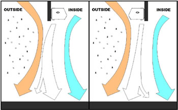
H. Regardless of whether the product is mounted on the
inside or outside of the door opening, set the air
directional vanes in the discharge nozzle slightly
outward to approximately 10-15° towards the outside,
or the wind load. (FIG. 5). |
|
|
|
|
|
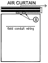
| Electrical
Field Wiring |
|
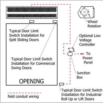
The
unit and any optional accessories must be wired with
the proper voltage to the junction box per the wiring
diagram. (FIG. 4, unheated products only) |
|
|
|
|
|
 |
|
|
|
|
 |
|
|
FIG. 5 |
|
|
|
|
I.
For products with control panels, turn the HOA
(Hand-On-Auto) selector switch to “On” position and
open the door to energize the product. For products
without a control panel or an On/Off switch, open the
door to energize the product. |
|
|
FIG.
4 |
|
|
|
|
|
| MAINTENANCE |
J.
If heated products are installed, reference Heated
Products Supplement.
K. For three phase units, verify direction of rotation of
blower wheels (note direction arrows on the blower
wheel housing). Correct if needed by changing polarity
of three phase power.
L. VERY IMPORTANT Using a clamp meter, measure
the amperage to each motor and ensure that they do
not exceed the amperage listed on the product label. |
|
|
 WARNING WARNING |
|
To
reduce the risk of fire, electrical shock or injury to
persons, observe the following:
A. Maintenance is to be performed only by qualified
personnel who are familiar with local codes and
regulations and are experienced with this type of
product.
B. Before servicing or cleaning the product switch power
off at service panel and lock service panel to prevent
power from being switched “ON” accidentally. |
|
|
M.
If applicable, adjust the air intake grille(s) such that
the output air stream reaches the floor.
For tem-
perature control and environmental separation
applications, the air stream should reach
the floor
with sufficient strength to create an air
seal around
the door opening without creating turbulent mixing
of the inside and outside air. For flying
insect control
applications, the air stream should reach
the floor with
maximum strength. If after proper installation
and
adjustment, the product appears to be producing
too little or too much air for the application,
contact
the manufacturer. |
|
|
Routine
maintenance is required to keep this product
operating at its peak performance and efficiency. Over
time, the housing, air intake grille, air intake filter, blower
wheels and motor(s) will accumulate a build up of dust,
debris and other residue. It is imperative to keep these
components clean. Failure to do so will not only lower
operational efficiency and performance, but also reduce
the useful life of the product. The time between cleanings
depends on the application, location and daily hours of use.
On average, under normal use conditions, the product
should require a thorough cleaning once every
six (6) months. |
|
|
|
|
|
|
| To
clean the product, perform the following: |
4.
Thoroughly clean the air intake grille(s)/filter(s).
5. Thoroughly wipe down the motor, blower wheels
and blower wheel housings. Be careful not to spray
the motor with a water hose.
6. The motor(s) require no additional lubrication. They
are permanently lubricated and feature double sealed
ball bearings.
7. To re-install the product, reverse the procedures above.
8. Reconnect the power source to the product.
9. If you have any questions regarding the maintenance
of the product, contact the manufacturer. |
1.
Verify the product has been disconnected from the
power source.
2. Use a damp cloth and either a warm mild soapy water
solution or bio-degradable degreaser, to wipe down the
exterior components of the housing.
3. To access the interior of the product, remove the air
intake grille(s) and/or air intake filter(s). This is
accomplished by removing the screws on the face of
the air intake grille(s)/filter(s). |
|
|
|
Commercial Air Curtains,
Air Curtain, Air Curtain Door, Air Curtain Heater, Air Curtains, Air Doors,
Door Air Curtains, Heat
Curtains, Mars Air Curtain, Mars Air Door, Warm Air Curtains, and Insect
Barrier from your source for material handling
equipment. |
Back
to Product Category |
 |
|


