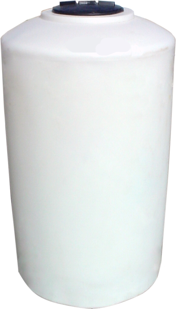
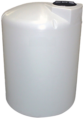
VERTICAL BULK STORAGE TANKS
|
|
 |
|
 |
|
45 gal. - 500 gal. (46x76),
550 gal. (45x94), and
750 gal. have center manways
All others have offset manways.
|
|
(1) Subject to stocking inventory
(2) IA Series available only in blue color
(3) 45 Gal. has inverted calibrations
(4) 55 Gal. has no calibrations and flat top
(5) 110 & 220 Gal. have side indents for fork lift handling |
|
|
|
|
|
IC – Commercial Series is designed to handle contents that have a maximum specific gravity of 1.5 at 73° F.
IA – Industrial Series is designed to handle contents that have a specific gravity of 1.9 at 73° F.
IX – Crosslinked Poly Series (x): Available upon request, contact sales office. (FOB Tn only).
• Translucent for convenient product level viewing.
• Flat bottom design provides for easy and cost efficient installation.
• ASTM-D-1998-91 Specification compliance available |
|
|
|
IMPORTANT- Review tank handling, installation & use guidelines, see below.
• The degree of translucency varies with wall thickness and tank color.
• Tank sizes are nominal. Capacities indicate approximate volume.
• Calibrations on molded tanks indicate approx. vol.
• Tanks UV stabilized for outdoor use. |
|
|
|
Click the button of the item you wish to purchase. Contact us for special lengths
|
Prices
|
|
|
Click Model No. to See Technical Drawing
|
Capacity (Gal)
|
Size
|
Vented Manway (in)
|
1C Tank Price
|
1A Tank Price
|
|
TA1628
|
20
|
16 x 28
|
8
|
~
|
~
|
|
|
22
|
20 x 20
|
8
|
|
~
|
|
|
25
|
18 x 29
|
5
|
|
~
|
|
TA1829
|
25
|
18 x 29
|
5
|
~
|
|
|
TA1841
|
40
|
18 x 41
|
5
|
~
|
|
|
|
45
|
18 x 51
|
4
|
|
|
|
|
50
|
18 x 53
|
5
|
|
~
|
|
|
55
|
20 x 38
|
8
|
|
|
|
|
65
|
23 x 42
|
8
|
|
|
|
|
65
|
24 x 46
|
8
|
|
|
|
|
65
|
23 x 43
|
8
|
|
~
|
|
|
75
|
23 x 49
|
8
|
|
|
|
|
75
|
23 x 49
|
8
|
|
~
|
|
|
100
|
23 x 64
|
8
|
|
|
|
|
100
|
28 x 43
|
8
|
|
~
|
|
|
105
|
23 x 63
|
8
|
|
~
|
|
TC3536 (5)
|
110
|
35 x 36
|
8
|
|
|
|
N-40318
|
120
|
38 x 31
|
5
|
|
~
|
|
N-44102
|
130
|
32 x 46
|
8
|
|
~
|
|
|
130
|
23 x 76
|
8
|
|
|
|
TA2382
|
135
|
23 x 82
|
8
|
~
|
|
|
|
150
|
30 x 56
|
8
|
|
~
|
|
|
160
|
28 x 66
|
8
|
|
|
|
|
165
|
31 x 58
|
8
|
|
|
|
|
165
|
31 x 56
|
16
|
|
~
|
|
TC4236
|
170
|
42 x 36
|
8
|
|
~
|
|
|
175
|
36 x 53
|
7
|
|
|
|
|
200
|
31 x 72
|
8
|
|
|
|
|
200
|
30 x 72
|
8
|
|
~
|
|
TA4048
|
210
|
40 x 49
|
5
|
~
|
|
|
|
210
|
32 x 67
|
16
|
|
|
|
TC3563 (5)
|
220
|
35 x 63
|
8
|
|
|
|
N-40320
|
220
|
42 x 44
|
5
|
|
~
|
|
TA3172
|
225
|
31 x 76
|
8
|
~
|
|
|
TC4642
|
250
|
46 x 42
|
8
|
|
|
|
|
250
|
35 x 68
|
8
|
|
|
|
|
250
|
30 x 89
|
8
|
|
~
|
|
|
300
|
35 x 81
|
16
|
|
|
|
|
300
|
35 x 87
|
16
|
|
|
|
|
300
|
42 x 59
|
16
|
|
|
|
|
300
|
45 x 60
|
16
|
|
|
|
TA3577
|
300
|
35 x 81
|
8
|
~
|
|
|
|
300
|
36 x 79
|
16
|
|
~
|
|
N-40302
|
305
|
46 x 49
|
16
|
|
~
|
|
|
310
|
32 x 94
|
16
|
|
~
|
|
TA4275
|
425
|
42 x 75
|
16
|
~
|
|
|
|
500
|
46 x 76
|
16
|
|
|
|
|
500
|
47 x 72
|
16
|
|
|
|
|
500
|
48 x 76
|
16
|
|
|
|
|
500
|
64 x 46
|
16
|
|
|
|
|
500
|
63 x 53
|
16
|
|
|
|
TA4676
|
500
|
46 x 76
|
8
|
~
|
|
|
TC6442
|
500
|
64 x 42
|
16
|
|
|
|
N-40148
|
500
|
48 x 73
|
16
|
|
~
|
|
N-40150
|
500
|
48 x 73
|
16
|
~
|
|
|
|
550
|
45 x 94
|
16
|
|
|
|
|
550
|
67 x 44
|
16
|
|
~
|
|
TA5266
|
550
|
52 x 66
|
8
|
~
|
|
|
|
600
|
52 x 66
|
16
|
|
|
|
|
650
|
56 x 70
|
16
|
|
|
|
(3) 45 Gal. has inverted calibratiions which indicates amount used.
(4) 55 Gal. has no calibrations and flat top
(5) 110 & 220 Gal. have side indents for fork lift handling
Polyethylene tanks may have some minor cosmetic imperfections due to the size and combination of mold sections that are used.
These imperfections have no effect on long-term tank performance or warranties.
Some models do not have technical drawings, please call us and we can provide them. |
Click the button of the item you wish to purchase. Contact us for special lengths
|
Click Model No. to See Technical Drawing
|
Capacity (Gal)
|
Size
|
Vented Manway (in)
|
1C Tank Price
|
1A Tank Price
|
|
|
700
|
64 x 60
|
16
|
|
|
|
|
750
|
46 x 119
|
16
|
|
|
|
|
750
|
48 x 103
|
16
|
|
~
|
|
|
850
|
48 x 124
|
16
|
|
|
|
|
850
|
48 x 118
|
16
|
|
~
|
|
|
850
|
54 x 92
|
8
|
|
|
|
TC6481
|
1000
|
64 x 81
|
16
|
|
|
|
|
1000
|
66 x 81
|
22
|
|
|
|
|
1000
|
69 x 74
|
16
|
|
|
|
N-40152
|
1000
|
64 x 80
|
16
|
|
~
|
|
N-40154
|
1000
|
64 x 80
|
16
|
~
|
|
|
|
1000
|
64 x 81
|
16
|
~
|
|
|
N-44111
|
1000
|
72 x 66
|
16
|
|
~
|
|
|
1100
|
87 x 53
|
16
|
|
~
|
|
N-40093
|
1100
|
87 x 53
|
16
|
~
|
|
|
|
1150
|
48 x 156
|
16
|
|
|
|
|
1150
|
86 x 57
|
16
|
|
|
|
|
1200
|
86 x 52
|
16
|
|
|
|
|
1500
|
64 x 121
|
16
|
|
|
|
|
1500
|
64 x 115
|
16
|
|
~
|
|
N-40146
|
1500
|
64 x 115
|
16
|
~
|
|
|
|
1500
|
64 x 115
|
16
|
|
|
|
|
1500
|
85 x 69
|
16
|
|
|
|
|
1550
|
87 x 65
|
16
|
|
|
|
|
1550
|
88 x 68
|
16
|
|
|
|
|
1550
|
87 x 65
|
16
|
|
~
|
|
N-40236
|
1550
|
87 x 65
|
16
|
~
|
|
|
|
1650
|
85 x 74
|
16
|
|
|
|
|
1700
|
86 x 74
|
16
|
|
|
|
|
1700
|
86 x 78
|
16
|
|
|
|
|
1700
|
87 x 74
|
16
|
|
~
|
|
N-40012
|
1700
|
87 x 74
|
16
|
~
|
|
|
|
2000
|
64 x 144
|
16
|
|
|
|
|
2000
|
64 x 152
|
16
|
|
~
|
|
N-47564
|
2000
|
64 x 152
|
16
|
~
|
|
|
|
2000
|
64 x 156
|
16
|
|
|
|
TA9083
|
2000
|
90 x 83
|
16
|
|
|
|
N-44125
|
2000
|
90 x 84
|
16
|
|
~
|
|
N-44127
|
2000
|
90 x 84
|
16
|
~
|
|
|
|
2100
|
87 x 87
|
16
|
|
|
|
|
2100
|
87 x 89
|
16
|
|
~
|
|
N-40241
|
2100
|
87 x 89
|
16
|
~
|
|
|
|
2100
|
102 x 69
|
16
|
|
~
|
|
|
2150
|
86 x 99
|
16
|
|
|
|
|
2200
|
86 x 96
|
16
|
|
|
|
|
2500
|
95 x 89
|
16
|
|
|
|
|
2500
|
95 x 92
|
16
|
|
|
|
N-40051
|
2500
|
95 x 91
|
16
|
|
~
|
|
N-40052
|
2500
|
95 x 91
|
16
|
~
|
|
|
|
2500
|
102 x 79
|
22
|
|
~
|
|
N-42384
|
2500
|
102 x 79
|
22
|
~
|
|
|
|
2500
|
90 x 100
|
16
|
|
|
|
|
2700
|
102 x 89
|
16
|
|
|
|
|
2800
|
95 x 98
|
16
|
|
|
|
|
3000
|
95 x 107
|
16
|
|
|
|
|
3000
|
90 x 120
|
16
|
|
|
|
N-40754
|
3000
|
95 x 109
|
16
|
|
~
|
|
N-40755
|
3000
|
95 x 109
|
16
|
~
|
|
|
|
3000
|
91 x 119
|
16
|
|
~
|
|
|
3000
|
102 x 93
|
16
|
|
~
|
|
N-42380
|
3000
|
102 x 93
|
16
|
~
|
|
|
N-43136
|
3000
|
102 x 93
|
22
|
|
~
|
|
N-43138
|
3000
|
102 x 93
|
22
|
~
|
|
|
Polyethylene tanks may have some minor cosmetic imperfections due to the size and combination of mold sections that are used.
These imperfections have no effect on long-term tank performance or warranties.
Some models do not have technical drawings, please call us and we can provide them.
|
|
Click the button of the item you wish to purchase. Contact us for special lengths
|
Click Model No. to See Technical Drawing
|
Capacity (Gal)
|
Size
|
Vented Manway (in)
|
1C Tank Price
|
1A Tank Price
|
|
|
3100
|
102 x 99
|
16
|
|
|
|
|
3200
|
95 x 112
|
16
|
|
|
|
|
3600
|
86 x 156
|
16
|
|
|
|
|
4000
|
95 x 140
|
16
|
|
|
|
|
4000
|
102 x 125
|
16
|
|
|
|
|
4000
|
102 x 125
|
16
|
|
~
|
|
|
4200
|
102 x 131
|
16
|
|
~
|
|
|
4300
|
120 x 105
|
16
|
|
|
|
|
4500
|
95 x 156
|
16
|
|
|
|
|
5000
|
102 x 152
|
16
|
|
|
|
N-40164
|
5000
|
102 x 152
|
16
|
|
~
|
|
N-40166
|
5000
|
102 x 152
|
16
|
~
|
|
|
|
5500
|
138 x 92
|
16
|
|
~
|
|
|
5600
|
120 x 138
|
16
|
|
|
|
N-40226
|
6000
|
102 x 182
|
16
|
|
~
|
|
N-40233
|
6000
|
102 x 182
|
16
|
~
|
|
|
N-40659
|
6100
|
119 x 140
|
16
|
|
~
|
|
N-40661
|
6100
|
119 x 140
|
16
|
~
|
|
|
|
6400
|
120 x 150
|
16
|
|
|
|
N-40224
|
6500
|
119 x 150
|
16
|
|
~
|
|
N-40232
|
6500
|
119 x 150
|
16
|
~
|
|
|
|
6500
|
120 x 147
|
16
|
|
~
|
|
N-42317
|
6500
|
120 x 147
|
16
|
~
|
|
|
TA7000
|
7000
|
142 x 125
|
16
|
~
|
|
|
N-40663
|
7800
|
119 x 176
|
16
|
|
~
|
|
N-40665
|
7800
|
119 x 176
|
16
|
~
|
|
|
|
8400
|
119 x 188
|
16
|
|
~
|
|
N-42062
|
8400
|
119 x 188
|
16
|
~
|
|
|
TA9500
|
9500
|
120 x 213
|
16
|
~
|
|
|
|
10000
|
141 x 160
|
16
|
|
~
|
|
N-43130
|
10000
|
141 x 160
|
16
|
~
|
|
|
|
11000
|
144 x 167
|
22
|
|
~
|
|
N-44011
|
11000
|
144 x 167
|
22
|
~
|
|
|
T10500
|
10500
|
142 x 177
|
16
|
~
|
|
|
N-43919
|
12000
|
141 x 193
|
16
|
|
~
|
|
N-43921
|
12000
|
141 x 193
|
16
|
~
|
|
|
|
12500
|
144 x 193
|
16
|
|
~
|
|
N-44017
|
12500
|
144 x 193
|
16
|
~
|
|
|
|
15000
|
141 x 244
|
16
|
|
~
|
|
N-43943
|
15000
|
141 x 244
|
16
|
~
|
|
|
N-43825
|
20000
|
165 x 242
|
22
|
|
~
|
|
N-43827
|
20000
|
165 x 242
|
22
|
~
|
|
Polyethylene tanks may have some minor cosmetic imperfections due to the size and combination of mold sections that are used.
These imperfections have no effect on long-term tank performance or warranties.
Some models do not have technical drawings, please call us and we can provide them. |
Click the button of the item you wish to purchase. Contact us for special lengths
|
|
|
|
|
|
|
|
|
TANK ACCESSORIES
|
|
|
|
|
|
|
|
|
|
| Insulated and Temperature Controlled Systems |
|
A system consisting of flexible heating panels, thermostat and rigid foam insulation, designed to
help control and maintain the temperature of the product inside of our tanks. (Contact our sales
dept. for complete details and price quotations) |
|
|
|
 |
|
|
|
|
|
|
|
| Electronic Heating Systems |
|
|
|
- Operate from 120 volts/AC power source
- Heater panels are located around tank for uniform heating
- All systems are custom designed, *Please supply anticipated minimum ambient temperature,
wind velocity, and the desired minimum temperature requirement of contents |
|
|
|
|
|
|
|
|
|
|
 |
|
| Rigid Insulation |
|
|
|
|
- 2" spray on rigid closed cell polyurethane foam
- R value of 7.8 per inch of thickness
- insulation and mastic coating have excellent weathering characteristics |
|
|
|
|
|
|
|
|
|
|
|
| Tie Down Kits |
|
|
|
|
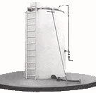
PVC coated wire cable and adjustable steel turn buckles provide an economical and effective
restraining system. |
|
|
|
|
|
|
|
|
|
|
|
|
|
|
|
|
|
|
|
|
|
 |
|
|
|
Model No.
|
Tank Size In Gallons
|
Prices
|
|
TC1700TK
|
1700 or less (except 750. 850. + 1500)
|
|
|
TC2000TK
|
2000 to 3200 (and 750. 850 + 1500)
|
|
|
TC3600TK
|
3600 & Larger
|
|
|
|
|
|
|
|
|
|
|
| Seismic Zone 4 Restraint Kits |
|
|
|
Tank tie down assembly for wind and earthquake protection. Seismic zone 4 - 1994 Uniform
Building Code. Contact sales office for complete details. |
|
|
|
|
|
|
|
|
|
Click the button of the item you wish to purchase. Contact us for special lengths
|
FITTING PRICES
|
|
|
|
|
Series
|
Type
|
Material
|
1/2"
|
3/4"
|
1"
|
1-1/4"
|
1-1/2"
|
2"
|
3"
|
4"
|
6"
|
|
Bolt-on Bulkhead Fittings Installed
|
|
*FZ
|
|
PVC
|
|
|
|
~
|
|
|
|
|
|
|
PP
|
|
|
|
~
|
|
|
|
|
~
|
|
CPVC
|
|
|
|
~
|
|
|
|
|
|
|
316 S.S
|
|
|
|
~
|
|
|
|
|
~
|
|
Bolt-on Bulkhead Fittings Loose
|
|
*FZ
|
|
PVC
|
|
|
|
~
|
|
|
|
|
|
|
PP
|
|
|
|
~
|
|
|
|
|
~
|
|
CPVC
|
|
|
|
~
|
|
|
|
|
|
|
316 S.S
|
|
|
|
~
|
|
|
|
|
~
|
|
Viton Gaskets
|
|
Viton Gaskets
|
For FA Series
|
1 Required
|
|
|
|
~
|
|
|
|
|
|
|
Bulkhead Fittings Installed
|
|
FA
|
|
PVC
|
|
|
|
~
|
|
|
|
|
~
|
|
PP
|
|
|
|
~
|
|
|
|
|
~
|
|
CPVC
|
~
|
~
|
|
~
|
|
|
|
|
~
|
|
316 S.S
|
~
|
|
|
~
|
|
|
|
~
|
~
|
|
Bulkhead Fittings Loose
|
|
FA
|
|
PVC
|
~
|
|
|
~
|
|
|
|
|
~
|
|
PP
|
|
|
|
~
|
|
|
|
|
~
|
|
CPVC
|
~
|
~
|
|
~
|
|
|
|
|
~
|
|
316 S.S
|
~
|
|
|
~
|
|
|
|
~
|
~
|
|
Viton Gaskets
|
|
Viton Gaskets
|
For FA Series
|
1 Required
|
|
|
|
~
|
|
|
|
|
~
|
|
Self-Aligning Bulkhead Install Teflon Seat (EPDM Gasket)
|
|
FC
|
|
PVC
|
~
|
~
|
|
~
|
~
|
|
|
~
|
~
|
|
Half Coupling Welded
|
|
FB
|
|
PE
|
|
|
|
~
|
|
|
|
|
|
|
PP
|
|
|
|
~
|
|
|
|
|
|
|
Full Coupling Welded
|
|
FD
|
|
PE
|
|
|
|
~
|
|
|
|
|
|
|
PP
|
|
|
|
~
|
|
|
|
|
~
|
|
Spigot Installed Needle Type
|
|
FE
|
|
PE
|
|
|
~
|
~
|
~
|
~
|
~
|
~
|
~
|
|
Spigot Installed Drum Type
|
|
FF
|
|
PE
|
~
|
|
~
|
~
|
~
|
|
~
|
~
|
~
|
|
Flange Assembly (Bulkhead fitting or half-coupling additional)
|
|
FY
|
|
PVC
|
|
|
|
|
|
|
|
|
|
|
Ball Valves True Union Threaded
|
|
FJ
|
|
PVC
|
|
|
|
|
|
|
|
|
~
|
|
Sight Gauge Installed
|
|
FL
|
|
PVC
|
|
|
|
~
|
|
|
~
|
~
|
~
|
|
Sight Gauge Float Indicator
|
|
GO
|
|
PVC
|
~
|
~
|
~
|
~
|
~
|
|
~
|
~
|
~
|
|
CAM Action Couplers
|
|
GA
|
|
PP (Glass Reinforced)
|
|
|
|
|
|
|
|
~
|
~
|
|
90 Degree Cam Action
|
|
GB
|
|
PP (Glass Reinforced)
|
~
|
~
|
~
|
~
|
|
|
~
|
~
|
~
|
|
Cam Action Adapter
|
|
GH
|
|
PP
|
|
|
|
|
|
|
|
~
|
~
|
|
Cam Action 90 Degree
|
|
GI
|
|
PP
|
~
|
~
|
~
|
~
|
|
|
~
|
~
|
~
|
|
Float Valve Installed
|
|
FK
|
|
PVC
|
~
|
|
~
|
~
|
~
|
~
|
~
|
~
|
~
|
|
U-Vent (Bulkhead or half coupling additional)
|
|
GC
|
|
PVC
|
~
|
~
|
~
|
~
|
~
|
|
|
|
~
|
|
Siphon Tube (Bulkhead or half coupling additonal)
|
|
GD
|
|
PVC
|
~
|
|
|
|
|
|
|
|
|
|
PP
|
~
|
~
|
~
|
~
|
~
|
|
|
~
|
~
|
|
External Down Fill Dome Mounted Internal Down
|
|
GE
|
|
PVC
|
~
|
~
|
~
|
~
|
~
|
|
|
~
|
~
|
|
External Down Fill Side Mounted (With Internal Down)
|
|
GF
|
|
PVC
|
~
|
~
|
~
|
~
|
~
|
|
|
~
|
~
|
|
Internal Down Pipe Fitting
|
|
GG
|
|
PVC
|
~
|
~
|
~
|
~
|
~
|
|
|
~
|
~
|
|
|
|
|
*Bolt-On Bulkhead Fittings – provides a secure, reliable connection to the tank. This style of fitting is recommended
on our larger bulk storage tanks. All bolting hardware is 316 stainless steel; titanium and hastal-loy "C" bolt material
is also available. |
Click the button of the item you wish to purchase. Contact us for special lengths
|
Manways
|
|
Series
|
Type
|
Material
|
8"
|
12"
|
16"
|
22"
|
22" Bolted
|
|
MW
|
Hinged Manway
|
PP
|
~
|
|
|
~
|
~
|
|
MW
|
Manway
|
PP
|
|
~
|
|
|
|
|
MW
|
Non-Vented Manway
|
PP
|
|
~
|
|
~
|
~
|
|
| 22" Bolted Manway has PE Foam Gaskets and SS Bolts |
|
|
MATERIAL SELECTION
|
|
|
We offer you a selection of materials that are by far the best suited for molded tanks and containers for use with
aggressive corrosive chemicals as well as food products. Our 35 plus years of experience in rotational molding,
combined with our professional staff of chemical, mechanical and plastics engineers, enables us to provide you
with the highest quality rotationally molded tanks and containers available in the industry.
The following is a brief description of these materials:
|
|
|
Polyethylene
A high quality thermoplastic that has outstanding resistance to both physical and chemical attack. The overall general
toughness and excellent chemical resistance to a wide array of wet and dry industrial chemicals and food products
make polyethylene ideally suited for storage tanks and containers.
|
|
Polyethylene is translucent and its natural color ranges from slightly off white to creamy yellow, depending on wall
thickness and type. Ultraviolet light stabilizers are added for use in outdoor applications. Colors are available on
request for a nominal up charge. BPA-Free Material. |
|
|
A) Linear Polyethylene
Linear Polyethylene is available as low, medium and high density. Most products offered in this catalog are molded
of linear medium density polyethylene (LMDPE) and linear high density polyethylene (LHDPE). They have superior
mechanical properties, high stiffness, excellent low temperature impact strength and excellent environmental stress
crack resistance. The linear polyethylene used meets specifications contained in FDA regulation 21CFR177.1520
(c) 3.1 and 3.2 and so may be used as an article or a component of articles intended for use in contact with food,
subject to any limitations in the regulations. Maximum operating temperature for linear polyethylene is 140° F. BPA-
Free Material.
|
|
|
B) Crosslinkable Polyethylene
Crosslinkable polyethylene is a high density polyethylene that contains a crosslinking agent which reacts with the
polyethylene during molding, forming a crosslinked molecule similar to a thermoses plastic. This reaction improves
toughness and environmental stress crack resistance. Crosslinked Polyethylene (XLPE) is not weldable and does
not meet FDA requirement 21CFR177.1520. Maximum operating temperature of crosslinked polyethylene is 150° F.
|
|
2) Polypropylene
Polypropylene is a rigid plastic that has a higher operating temperature limit than polyethylene: 212° F. It offers good
chemical resistance, has a high resistance to stress crack, and is autoclavable. Polypropylene (PP) is not recommended
for applications in sub-freezing temperature or where high impact strength is needed. A rough, irregular interior surface
is common characteristic of molded polypropylene. |
|
| Considerations to Material Selection |
|
Elevated Temperatures
Continued or prolonged service with contents at elevated temperatures can shorten the life of a tank. The effects of
the temperature will depend on the chemical content and its specific gravity, tank size and configuration, material of
construction, wall thickness and if there are any external supports on the tank. |
|
Exposure to Ultraviolet Light
Unprotected thermoplastics exposed to sunlight for an extended period of time, absorb ultraviolet (UV) light, which
can cause discolorations, embrittlement and eventual cracking. Fluorescent lighting has a similar effect. Elevated tem-
peratures can accelerate the embrittling process. These products are molded from materials utilizing the latest
technology for UV stabilizers which greatly reduce the harmful effects of UV light. For greater protection, keep tanks
out of direct sunlight or order dark colored tanks which will further retard the effect of UV light. |
|
Environmental Stress Cracking
Certain surface active materials, although they have no chemical effect on polyethylene, can accelerate its cracking
when under stress, such as liquid detergents and ultra pure water- (see our chemical compatibility Chart.)
Elevated temperatures tend to accelerate the cracking. Although all polyethylenes are subject to stress cracking,
some are more resistant to it than others. The degree of stress on the plastic has a direct bearing on its resistance,
therefore a tank and system should be designed to minimize stress. Chemtainer.com tanks are molded visually stress
free, employing materials that are highly resistant to environmental stress cracking, and hence are less prone to cracking
than fabricated tanks. Stress cracking agents are surface active materials. Proper care should be taken to reduce stress
at fillings, bands, tie down lugs, etc. |
|
| Characteristics and Physical Properties |
|
|
General Characteristics
|
|
|
|
Linear
|
|
XLPE
|
|
PP
|
Maximum Service Temp
Chemical Resistance
Stress Crack Resistance
General Toughness
Impact Resistance
Abrasion Resistance
Rigidity
Color
FDA Compliance
Outdoor Use
Weildable
Recyclable |
|
|
|
140 F (60 C)
Very Good
Excellent
Very Good
Excellent
Good
Good
WH
Translucent
Yes
Yes
Yes
Yes |
|
|
150 F (65 C)
Very Good
Excellent
Very Good
Excellent
Good
Good
Off WH Trans
No
No
No
No
|
212 F (100 C)
Very Good
Excellent
Fair
Poor
Good
Good
Off WH
Opaque
Yes
Yes
Yes
Yes
|
|
Physical Properties
(Nominal Values)
|
|
Linear |
|
|
XLPE |
|
|
PP |
| Density (gm/cc) ASTM:D1505 |
|
|
0.937-0.942
|
|
|
0.937-0.942
|
|
0.901-0.905
|
Environmental Stress
Cracking (F-50hrs)
ASTIM:D1693 |
|
|
>1,000
|
|
|
>1,000
|
|
>1,000
|
Tensile Strength ASTIM:D638
Ultimate 2"/Min (PSI) Type IV |
|
2,600
|
|
|
2,600
|
|
|
3,000
|
Elongation at Break ASTIM:D638
2"/Min(%) Type IV |
|
450
|
|
|
450
|
|
|
5
|
| Flexural Modulus (PSI) ASTIM:D790 |
|
100,000-110,000
|
|
|
100,000-110,000 |
|
|
90,000-100,000
|
| Brittleness Temp ASTIM:D746 |
|
<-94F (-70 C)
|
|
|
-180 F (-118 C)
|
|
|
32 F (0 C)
|
| VICAT Softening Temp ASTIM:D152B |
|
240F |
|
|
240F |
|
|
300F |
|
|
|
|
|
|
|
|
|
|
|
|
|
|
|
|
FITTING LOCATIONS GUIDE
|
|
|
|
|
|
|
|
|
|
|
|
|
|
|
|
|
|
|
|
|
|
|
|
|
|
|
|
|
|
| Specifying Fitting Locations |
|
|
|
|
|
|
|
|
|
|
|
|
|
|
|
|
|
|
|
|
|
|
|
|
|
|
|
|
|
|
|
|
|
|
|
|
|
|
|
|
|
|
|
|
It is very important to be as precise as possible when specifying tank fittings and accessories. Location, type and size
of fittings must be noted clearly on your drawing. If more than one fitting is being specified, mark each fitting with a
letter A, B, C etc. Dimensional drawings are available for all tanks. Download a blank generic drawing and send or
fax in with your order. |
|
|
|
|
|
|
|
|
|
|
|
|
|
|
|
|
|
|
|
|
|
|
|
|
|
|
|
|
|
| Vertical Bulk Storage Tanks |
|
|
|
|
|
|
|
|
|
|
|
|
|
|
|
|
|
|
|
|
|
|
|
|
|
|
|
|
|
|
|
|
|
|
|
|
|
|
|
|
|
|
|
|
 |
|
|
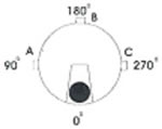
Plan View Calibration strip is at 0 degrees, in line with manway. Specify in degrees
from 0 the location of fittings. |
|
|
|
|
|
|
|
|
|
|
|
|
|
|
|
|
|
|
|
|
|
|
|
|
|
|
|
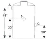
Elevation View Indicate in inches the height
from the center of the fitting to the floor. |
|
 |
|
|
|
|
|
|
|
|
|
|
|
|
|
|
|
|
|
|
|
|
|
|
|
|
|
|
|
|
|
|
|
|
|
|
|
|
|
|
|
Example: Fitting A is at 90°, 48 up from button; Fitting B is at 180°, 30 up from bottom;
Fitting C is at 270°, 20 up from bottom.
Note: Use a dotted circle to indicate fittings which are on the opposite side of the elevation
drawing (see fitting B) |
|
|
|
|
|
|
|
|
|
|
|
|
|
|
|
|
|
|
|
|
|
|
|
|
|
|
|
|
|
|
|
|
|
|
|
|
|
Most vertical storage tanks have 8 x8 flat sections at least every 90 degrees along the circumference at the bottom
of the side. These flats are ideal locations for bulk head fittings. |
|
|
|
|
|
|
|
|
|
|
|
|
|
|
|
|
|
|
|
|
|
|
|
|
|
|
|
|
|
| Horizontal Tanks |
|
|
|
|
|
|
|
|
|
|
|
|
|
|
|
|
|
|
|
|
|
|
|
|
|
|
|
|
|
|
|
|
|
|
|
|
|
|
|
|
|
|
|
|
|
|
|
|
|
|
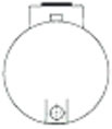
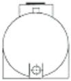
End View Round Horizontal
|
|
|
End View Leg Horizontal
|
|
|
|
|
|
|
|
|
|
|
|
|
|
|
|
|
|
|
|
|
|
|
|
|
|
|
|
|
|
|
|
|
|
|
|
|
|
|
|
|
|
 |
|
|
|
|
|
 |
|
|
|
|
|
|
|
|
|
|
|
|
|
|
|
|
|
|
|
|
|
|
|
|
|
|
|
|
|
|
|
|
|
|
|
 |
|
|
|
|
|
|
|
|
|
|
|
|
|
|
|
|
|
|
|
|
|
|
|
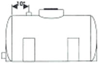
Side View |
|
|
|
Drain fittings are generally located in one of the ends of the tank, close
to the bottom. Indicate in inches any fitting(s) that are required in the
top of the tank. |
|
|
|
|
|
|
|
|
|
|
|
|
|
|
|
|
|
|
|
|
|
|
|
|
|
|
|
|
|
|
|
|
|
|
|
|
|
|
|
|
|
|
|
|
|
|
|
|
|
|
 |
|
|
Cylindrical Open Top Tanks |
|
|
|
|
|
|
|
|
|
|
|
|
|
|
|
|
|
|
|
|
|
|
|
|
|
|
|
|
|
|
|
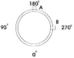
Plan View if more than one fitting is being specified, indicate in degrees the
location of the fittings. |
|
|
|
|
|
|
|
|
|
|
|
|
|
|
|
|
|
|
|
|
|
|
|
|
|
|
|
|
|
|
|
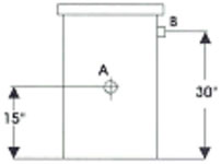
Elevation View indicate in inches the height from center of the fitting to the floor. |
|
|
|
|
|
|
|
|
|
|
|
|
|
|
|
|
|
|
|
|
|
|
|
|
|
|
|
|
|
|
|
|
|
|
|
|
|
|
|
|
|
|
|
|
|
|
|
|
|
|
|
|
|
|
 |
|
|
Example: Fitting A is at 180°, 15 up from bottom; Fitting B is at 270°,
30 up from bottom.
Note 1: Use a dotted circle to indicate fittings which are on opposite
side of the elevation drawing (see fitting A )
Note 2: Never include tank flange in your measurements. |
|
|
|
|
|
|
|
|
|
|
|
|
|
|
|
|
|
|
|
|
|
|
|
|
Rectangular Tanks |
|
|
|
|
|
|
|
|
|
|
|
|
|
|
|
|
|
|
|
|
|
|
|
|
|
|
|
|
|
|
 |
|
|
|
|
|
|
|
|
|
|
|
|
|
|
|
|
|
|
|
|
|
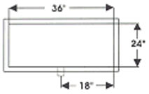
Indicate width, length and height of tank using inches.
Plan View indicate in inches the distance from edge of tank. |
|
|
|
|
|
|
|
|
|
|
|
|
|
|
|
|
|
|
|
|
|
|
|
|
|
|
|
|
|
|
|
|
|
|
|
|
|
|
|
|
|
|
|
|
|
|
|
|
|
|
|
|
|
|
|
|
|
|
|
|
|
|
|
|
|
|
|
|
|
|
 |
|
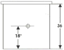
Elevation View indicate in inches the height from the center of the fitting to the
floor. |
|
|
Example: 24 x 36 x 36 HT. Fitting is 18 in from side along the 36 wall,
18 up from floor.
Note: Never include tank flange in your measurements
|
|
|
|
|
|
|
|
|
|
|
|
|
|
|
|
|
|
|
|
|
| Cylindrical Cone Bottom Tanks |
|
|
|
|
|
|
|
|
|
|
|
|
|
|
|
|
|
|
|
|
|
|
|
|
|
 |
|
|
|
|
|
|
|
|
|
|
|
|
|
|
|
|
|
|
|
|
|
|
|
|
|
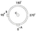
Plan View if more than one fitting is being specified, indicate in degrees the location
of the fittings. |
|
|
|
|
|
|
|
|
|
|
|
|
|
|
|
|
|
|
|
|
|
|
|
|
|
|
|
|
|
|
|
|
|
|
|
|
|
|
|
|
|
|
|
|
|
 |
|
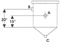
Elevation View Indicate in inches the height from the bottom of the straight side
to the center of the fitting. Do not include the cone. Stands have a lip 16 high.
Consult our sales dept. for minimum height of side fittings. |
|
|
|
|
|
|
|
|
|
|
|
|
|
|
|
|
|
|
|
|
|
|
Example: Fitting A is a 0°, 15 up the straight side; fitting B is at 90°, 20 up from straight side; C is in cone flat. |
|
|
|
|
|
|
|
|
|
|
|
|
|
|
|
|
|
|
|
|
|
|
|
Tank Handling Installation and Use Guidelines
|
|
Although our tanks are extremely durable, improper handling and installation can result in damage to tank, fittings,
and accessories. Failure to comply with handling and installation instructions voids all warranties.
1. At delivery, inspect your tank immediately for defects or shipping damage. Any discrepancies, or product problems,
should be noted on both the driver’s bill of lading and your packing list.
2. When unloading your tank from the delivery truck, avoid its contact with sharp objects. Forklift blades can cause
significant damage if proper precautions are not taken. Do not allow tanks to be rolled over on the fittings. Large
bulk storage tanks, whenever possible, should be removed from truck bed by use of a crane or other suitable lifting
device. OSHA regulation 29CFR 1910.178 through 1910.189 addresses specific standards for hoisting and lifting.
Keep unloading area free of rocks, sharp objects, and other materials that could damage the tank. If tank is unloaded
on it’s side, carefully brace to prevent rolling.
3. Support bottom of tank firmly and completely. Concrete pads provide the best foundation. However, when seismic
and wind factors are not being considered, tanks with a base load bearing of less than 800 pounds per square foot
require a firm, even, compacted bed of sand, pea gravel, or fine soil that won’t wash away. Tanks with a base load
bearing of 800 pounds per square foot, or greater, require a reinforced concrete base. Steel support stands concent-
rate the loaded tank weight onto the stand leg pads. It is recommended that stands are mounted on a concrete base.
Bolting of stands is necessary to prevent movement due to agitation, wind, seismic loads and accidental contact.
4. Install tanks in an area that is accessible. Ease of maintenance and removal should be considered.
5. Test by filling tank with water prior to use, to prevent material loss through unsecured fittings, shipping damage, or
manufacturing defects. Tanks should be tested for a minimum 5 hours.
6. Plastic screw on bulkhead fittings are designed to be hand tightened. Over tightening can cause fittings to leak.
7. Support sides of rectangular tanks. In general, tanks with heights greater than 18" must be supported. However,
specific applications must be considered: smaller tanks with contents that have high specific gravity and/or elevated
temperatures must be supported.
8. Do not mount heavy equipment on tank sides.
9. Do not allow weight on tank fittings. Fully support pipes and valves.
10. Use expansion joints to prevent damage at fittings from the differential expansion and contraction of the piping and
tanks.
11. Tanks are designed for use only in the atmospheric storage of chemicals, never for vacuum or pressure applications.
12. Immersion heaters should never touch the walls of the tank. Minimum spacing should be 3" - 4" from wall.
13. Refer to the chemical capability chart we can get for you, as a guide. Be certain tank, fittings, and fitting gasket
material are compatible with chemicals at the anticipated operating temperatures. Contact our technical staff for
information on chemicals not listed, or when uncertain conditions exist.
14. Protect tanks from impact, especially at temperatures below 40° F.
15. Confined spaces must be considered hazardous. Do not enter tank without first taking proper precautions.
16. Tank sizes as listed are nominal and calibrations on molded tanks are only approximates, but provide an indication
of volume. Polyethylene tanks expand and contract which will effect volume. The degree in which this occurs
depends on the size of the tanks, wall thickness, specific gravity of contents, temperature of contents and ambient
temperatures. |
|
|
STORAGE TANK SPECIFICATIONS
|
|
|
|
|
|
1.0 DESCRIPTION OF TANK
1.1 SPECIFICATIONS
1.2 GENERAL
These are one piece tanks, rotationally molded of linear medium or high density polyethylene or high density
crosslinkable polyethylene (XLPE). Refer to material type in the tank charts for availability. Tanks come in a
variety of shapes, are available in closed head designs with flat bottom (IC, IA & IX series), conical bottom
(JA & JC series), round horizontal (LC & LA series) or oval horizontal (MC & MA series).These tanks can
be furnished with various accessories as per customer specifications and are capable of holding aggressive
chemicals at atmospheric pressure. Open top mixing and processing tanks are available in cylindrical, conical
bottom and rectangular designs.
2.0 MATERIALS
2.1 LINEAR POLYETHYLENE
A high quality, chemically resistant plastic with high stress crack and impact resistance. Linear polyethylene is
translucent and exhibits properties that are ideal for applications that are exposed to low temperatures and/or
high impact. Unlike thermosets, linear polyethylene is weldable, thus allowing for greater flexibility when
designing modification to our standard tanks. The plastic complies with USDA and FDA regulations for storage
and processing of food. Linear polyethylene is fully recyclable and thereby provides a convenient method of
disposal.
2.2 CROSS-LINKED POLYETHYLENE
High density cross-linked polyethylene has excellent low temperature impact and environmental stress-crack
resistance. This polyethylene is a thermoset, thus does not permit the utilization of welded tank connections.
Cross-linked polyethylene does not have USDA or FDA compliance for storage of processing edibles and is
not recyclable.
2.3 ULTRA VIOLET LIGHT STABILIZERS AND FILLERS
The plastic does contain a minimum of 0.25 to a maximum of 0.50 long term U.V. stabilizer. It does not contain
any fillers.
2.4 PIGMENT
Pigment can be added at purchaser's request. These pigments would be compatible with the polyethylene and
will not exceed 0.5% dry blended and 2% compounded in of the total weight.
3.0 TANK CONSTRUCTION
3.1 MECHANICAL PROPERTIES
The minimum for the properties of the material shall be as follows based on molded parts:
|
|
|
|
|
|
PROPERTY
|
ASTM
|
VALUE
|
UNITS
|
|
|
|
|
|
Density
ESCR Spec. Thickness
125 Mils F-50
Tensile Strength
Ultimate 2"/min.
Elongation at break
2"/min.
Vicat Softening Temp.
Brittleness Temp.
Flexuarl Modulus
|
D1505
D1693
D638
Type IV Spec.
D638
Type IV Spec.
D1525
D746
D790
|
59 (0.937 - 0.942)
1000
2600
450
240
-180
100,000-110,000
|
#/ft3((gm/cc)
Hrs.
PSI
%
Deg. F
Deg. F
PSI
|
|
|
|
|
3.2 APPEARANCE
The finished surface of the tank shall be free as commercially practicable from visual defect such as foreign
inclusions, air bubbles, pin holes, craters, crazing and cracking that will impair the serviceability of the tank.
3.3 CUT EDGES
All edges cut out i.e., open top flanges, manways, shall be trimmed to have smooth edges.
3.4 DIMENSIONS AND TOLERANCES
General - all dimensions will be taken with the tank in its proper, usable position and unfilled. Tank dimensions
will represent the exterior measurements.
3.4.1 Outside diameter -- The tolerance for the outside diameter including out of roundness, shall be +/-3%.
3.4.2 Shell wall and head thickness - The tolerance for thickness shall be +/-20% of the design thickness. The
total amount of an area on the low side of the tolerance shall not exceed 10% of the total area and individual
area shall not exceed 1 ft. 2 (.09m2) in size.
3.5 PERFORMANCE REQUIREMENTS
The following performance requirements shall be conducted on samples taken from the manway cut out area or
where fittings are inserted in each tank
3.5.1 Low Temperature Impact Low temperature impact is determined by using a 30 lb. Falling dart at -20
degrees F. |
|
|
|
|
|
Wall thickness in. (mm)
|
ft-lb. (J) to fail.
|
|
|
|
|
|
Less than & including 0.25 in.(6.6 mm)
0.26 in.(6.6 mm) to & including 0.50 in.(12.9 mm)
0.51 in.(12.9 mm) to & including 0.75 in.(19.3 mm)
0.76 in.(19.3 mm) to & including 1.00 in.(25.4 mm)
|
90 (122.0)
100 (135.5)
150 (203.2)
200 (271.0)
|
|
|
|
|
3.5.2 Percent Gel - for crosslinked polyethylene
The percent gel level is determined by using the test method found in ASTM
D1998. The percent gel level for crosslinked tanks on the inside
0.125 in. (3.2mm) of the wall shall be a minimum of 60%.
3.5.3 Visual Inspection - The tank is visually inspected to determine such qualities as are discussed in Section
3.2, Appearance.
4.0 MARKINGS
4.1 The tank is marked to identify the producer, date (month and year) of manufacture, capacity
and serial number.
4.2 The proper caution and/or warning signs are affixed to the tank
4.3 Tank capacities should be based on total tank volume.
5.0 PACKAGING AND SHIPPING
5.1 All fittings and flange faces shall be protected from damage by covering with suitable plywood, hard-board or
plastic securely fastened. Tanks shall be vented at all times.
5.2 Pipe and tubing, fittings and miscellaneous small parts shall be packaged. Loose items which may scratch the
interior surface shall not be placed inside the tank during shipment. Additional protection, such as battens, end
wrapping, cross bracing, or other interior fastenings may be required to assure each individual equipment pieces
are not damaged in transit.
5.3 Upon arrival at the destination, the purchaser is advised to inspect for damage in transit. If damage has occurred,
a claim should be filled with the carier by the purchaser. The supplier should be notified if the damage is not first
repaired by the fabricator prior to the product being put into service. The purchaser accepts all future responsi-
bility for the effect of the tank failure resulting from damage.
5.4 It is recommended that the tank be hydrostacially tested at the time of installation. |
|
Vertical Bulk Storage Tanks, Storage Tanks, Vertical Bulk Tanks, Polyethylene Tanks, Commercial Series Vertical Tanks,
Industrial Series Vertical Tanks, and Tanks from your source for material handling equipment.
|
|